
URDF + Darwin Mini
URDF (Unified Robot Description Format) is an XML-based DSL to describe robots, commonly used in ROS (Robot Operating System). In this post, I describe how I wrote the URDF description of the ROBOTIS Mini humanoid robot (previously known as Darwin Mini) by ROBOTIS Co. Ltd.
The great thing about ROS is the availability of plenty of Tutorials to get started, and this is true for URDF. I will therefore not go through all the details, but rather try to give an overview of the approach I took, as it could be applied to other robots as well.
ROBOTIS has kindly made available the 3D model (in STL format) for Darwin-Mini, which comes handy when it comes to describe the robot.
Visualising the model
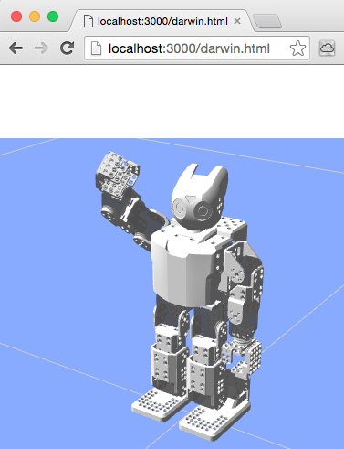 It is very important when building the URDF description, to constantly visualise it, to make sure we are on the right track. The most common approach to visualise an robot in ROS is through RViz. However, being on Mac OS X (where it is a pain to build ROS graphical tools like RViz), I chose another way: render the 3D model in my browser, using the very cool ros3djs ROS package, based on three.js.
As you can see, I have a little Jetty server (actually a Clojure ring server!) running on port 3000, which serves a static HTML page displaying the 3D view. The browser connects to a WebSocket interface (see rosbridge_suite package) to obtain coordinate frames of all 3D objects in real-time (see TF package).
Building our model
OK, now that we have our infrastructure in place to visualise a model, we need to create it.
I actually built it progressively, one piece after another. An URDF description is in fact a tree, were the root is the base link (which is normally attached to the world), and other links attached to the base link and to each other to form branches. For example, the body structure has multiple branches: the head, 2 arms and 2 legs. Pretty straightforward.
 In order to build the tree, I started with just one link, displayed it in the Web Viewer, tweaked its orientation, then attaching another link to it. And so on.
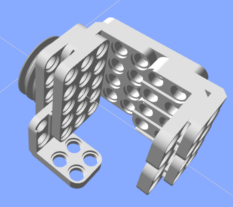
I started by building the hand. As you can see, all pieces are tight to each other, so the links are attached to each other through what is called a "fixed" joint (as opposed to moving joints).
Defining joints
So, for example, here is what we have:
    <joint name="body_torso_joint" type="fixed">
      <origin xyz="0 0 0" rpy="0 0 0" />
      <parent link="body_skeleton_link"/>
      <child link="body_torso_link"/>
    </joint>
    <link name="body_torso_link">
      <visual>
        <origin xyz="0 0 0" rpy="0 0 0" />
        <geometry>
          <mesh filename="package://darwin_description/meshes/DMF-B01(W).stl" scale="0.001 0.001 0.001" />
        </geometry>
        <material name="White" />
      </visual>
    </link>
Typically, a part (body_torso_link) is attached to the parent part (body_skeleton_link) through a "fixed" joint. The <visual> tag refers to the STL mesh of the part being described, and <material> applies the color.
 Let us look at moving joints now. In URDF, there are multiple kinds of moving joint: floating, revolute or prismatic. For Darwin Mini, we only have revolute joints.
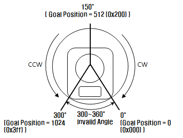
When defining the "revolute" joints, we need to take into account the acceptable angle range of the XL-320 servos, and the fact that the “normal” (rest) position of our robot is at 150°.
Also, there are 2 situations: (1) the body of the servo is fixed and the rotating axis is connected to the child link; (2) the rotating axis is attached to the parent link and the body of the servo is rotating. Abstracting away the geometry of the servos, here is what we get for case (1):
    <joint name="neck_servo_joint" type="fixed">
      <origin xyz="0 0 0" rpy="0 0 0" />
      <parent link="body_link"/>
      <child link="neck_servo_link"/>
    </joint>
    <link name="neck_servo_link">
      <visual><!-- ... --></visual>
    </link>
    <joint name="neck_joint" type="revolute">
      <axis xyz="0 0 1" />
      <limit lower="0" upper="${300*M_PI/180}" effort="${XL320_MAX_TORQUE}" velocity="${XL320_MAX_VELOCITY}" />
      <origin xyz="0 0 0" rpy="0 0 ${-150*M_PI/180}" />
      <parent link="neck_servo_link"/>
      <child link="neck_link"/>
    </joint>
    <link name="neck_link" />
Notice the body of the servo (neck_servo_link) is fixed to the parent link through neck_servo_joint, and we define a “dummy” link (neck_link) attached to the revolute joint (neck_joint). Child links will then be attached to this dummy link.
Parametrise and modularise the robot model
When starting to build up our model, the code quickly becomes very long and verbose. A common way to address this complexity in URDF descriptions is to make use of xacro (XML macro system) to define a model in a modular way.
We can define each basic part as a xacro block, with a few parameters. Each block has a ${name} (which will be used as prefix for the joint and link names) and a ${parent} to which the child link will be attached. Moreover, to describe symmetric parts, a nice trick I found (in PR2 description) is to pass a ${side} (“l” or “r” for “left” / “right”) and a ${reflect} parameter which takes a value of “1” for left side and “-1” for right side. This ${reflect} comes handy for example when rotating the part in opposite directions for left and right sides.
Here is an example:
  <xacro:macro name="darwin_spu5" params="name parent xyz rpy">
    <joint name="${name}_joint" type="fixed">
      <origin xyz="${xyz}" rpy="${rpy}" />
      <parent link="${parent}"/>
      <child link="${name}_link"/>
    </joint>
    <link name="${name}_link">
      <visual><!-- ... --></visual>
    </link>
  </xacro:macro>
Putting it all together
Here are the xacro files I end up with:
materials.urdf.xacro # materials (colors) used in basic blocks
common.urdf.xacro    # basic blocks (1 per 3D part)
servo.urdf.xacro     # servo motor & revolute joints
hand.urdf.xacro      # hands
arm.urdf.xacro       # arms to which hands are attached
leg.urdf.xacro       # legs and foots
body.urdf.xacro      # body to which arms & legs are attached
base.urdf.xacro      # base where the body is attached
darwin.urdf.xacro    # main file --includes all the files above
Next steps
So far, I explained how I built the URDF description for Darwin Mini. The next step will be to “gazebo-ise” the model (make it an SDF) so that it can be simulated in Gazebo, and eventually used to control the real Darwin Mini robot.